Experiment
3. Complex formation and dissociation of Cu2+, Co2+,
and Ni2+
ions
in ion exchangers8)
a.
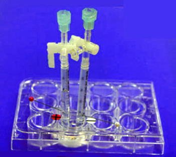
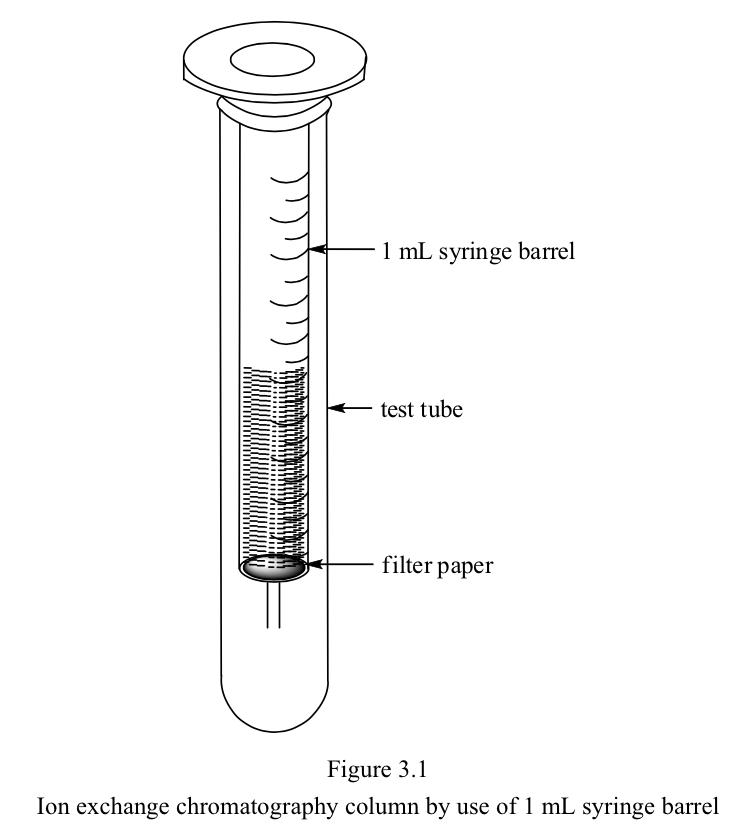
Preparation of ion exchange column
One mL of disposable plastic syringe barrel as shown above may be used
for this experiment.
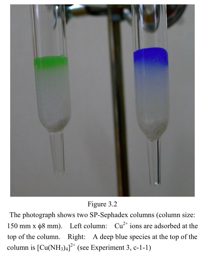
However, the use of larger column (150 mm x φ8 mm) is recommended for
improving visibility (Figure 3.2).
A small cotton ball is placed at the narrow neck of the column
end.
In this case, approximately 2 mL of ion exchanger is packed in the
column.
It is not necessary to attach the stopcock, since air does not
penetrate into the exchanger bed at least within 24 hours.
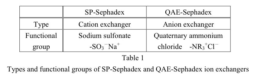
b. Equipments
and reagents
SP-Sephadex column (Na+ form) (2)
QAE-Sephadex column (Cl- form) (2)
Reagents
0.05 mol/L CuSO4
solution
0.05 mol/L CoSO4
solution
0.05 mol/L NiCl2
solution
4 mol/L NH3
solution
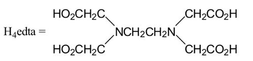
0.2 mol/L EDTA (Na2H2edta)
solution
3% H2O2
solution
0.12 mol/L NaCl solution
2 mol/L NaCl solution
0.10 mol/L HCl solution
c-1.
Experiment using SP-Sephadex column
c-1-1. Formation of copper(II)-EDTA complex
0.5 mL of 0.05 mol/L CuSO4 solution is added to an
SP-Sephadex column.
Cu2+ ions are adsorbed at the top of the column (Figure 3.2).
The column is washed with 0.5 mL of water.
Then, 0.5 mL of 4 mol/L NH3 solution is added to the
column.
The top of the column will show deep blue color, since [Cu(NH3)4]2+
complex ions are formed and remain at the top of the column
(Figure
3.2).
After the column is washed with 0.5 mL of water, 0.5 mL of 0.2 mol/L
EDTA solution is added to the column to form copper(II)-EDTA
complex
([Cu(edta)]2-).
The ion exchanger cannot adsorb the complex ions, since the complex
ions bear negative charge.
The complex ions move downward as a very broad band.
Water is added to the column, the fraction of the deep blue band is
collected as eluate A.
The column is regenerated with 2 mol/L NaCl solution and washed with
sufficient amount of water.
c-1-2.
Formation of cobalt(II)-EDTA complex
By use of 0.05 mol/L CoSO4 solution instead of 0.05
mol/L CuSO4
solution, similar experimental procedures to those of c-1-1
are
repeated.
When 0.5 mL of 0.05 mol/L CoSO4 solution is added to
the column, a pink band appears at the top of the column.
When 0.5 mL of 4 mol/L NH3 solution is added to the
column, the color
of the adsorbed band changes immediately from pink to blue
and then
gradually to brown.*1
When 0.5 mL of 0.2 mol/L EDTA solution is added to the column, the
adsorbed cobalt species give pale reddish violet cobalt(II)-EDTA
complex ions ([Co(edta)]2-) which move downward.*2
The column is washed with water and the reddish violet fraction is
collected (eluate B).
The column is regenerated with 2 mol/L NaCl solution and water as
described in c-1-1.
c-1-3.
Formation of nickel(II)-EDTA complex
By use of 0.05 mol/L NiCl2 solution instead
of 0.05 mol/L
CuSO4 solution, similar procedures to those of c-1-1 are
repeated.
When o.5 mL of 0.05 mol/L NiCl2 solution is added to
the column, a pale
green band of Ni2+ appears at the top of the column.
Addition of 0.5 mL of 4 mol/L NH3 solution causes the
color change of the adsorbed band from pale green to blue.
Addition of 0.2 mol/L EDTA solution results in formation of deep blue
[Ni(edta)]2- complex ions and this fraction is collected
as eluate C.
c-1-4.
Preparation of a mixture of [Cu(edta)]2-and [Co(edta)]2-
When 0.4 mL of 0.05 mol/L CuSO4 solution and 0.2 mL of
0.05 mol/L CoSO4
solution are mixed, almost colorless solution is obtained.
Addition of this solution to the column does not
show any color in the
exchanger bed.
However, when 0.5 mL of 0.2 mol/L EDTA solution is added to the
column,
a deep bluish violet band appears due to the formation
of [Cu(edta)]2-
and [Co(edta)]2- complexes which can be eluted with water.
The eluate
is named as D.*3
c-1-5. Oxidation of [Co(edta)]2- to
[Co(edta)]- by H2O2 solution
0.2 mL of 3% H2O2 solution
is added to the eluate D.
The solution is heated in a boiling water bath (a 50 mL conical
beaker) for 10 min.
Observe the color change of the solution. It will be recognized
that the color is considerably strengthened (solution E).
For eluate A and B, repeat similar experiments with
3% H2O2 solution.
It will be shown that [Cu(edta)]2- does not undergo any
reaction, while [Co(edta)]2- undergoes oxidation to
[Co(edta)]-.*4
c-2.
Experiment using QAE-Sephadex
c-2-1.
Separation of the mixture of [Cu(edta)]2- and [Co(edta)]-
(solution E) with NaCl solutions
Half of the solution E is
added to a QAE-Sephadex column which is then washed with 0.5 mL of
water.
The adsorbed species are eluted with 0.12 mol/L NaCl solution.
The reddish violet band ([Co(edta)]-) moves downward faster
than the
blue band ([Cu(edta)]2-).*5
The fraction of [Co(edta)]- is
collected.
c-2-2. Separation of the mixture of [Cu(edta)]2
- and [Co(edta)]- (solution E) with HCl solutions
The rest of the solution E is
added to another QAE-Sephadex column.
The complexes are adsorbed at the top of the column which is washed
with 0.5 mL of water.
When 0.10 mol/L HCl solution is added to the column, the band is
separated into a blue band and a reddish violet band.
The blue band (Cu2+) moves downward faster than the reddish
violet band ([Co(edta)]-).
The fraction of blue band is collected.
Then, the fraction of
reddish violet band is eluted and collected with 2 mol/L NaCl
solution.*6
d
Comments
*1 Although the reaction of Co2+ with NH3
solution is
complex, major products are cobalt(II) hydroxide, cobalt(II)-ammine
complexes, and dioxygen complex ([Co(NH3)5O2Co(NH3)5]4+).
*2 Upon the addition of excess EDTA solution, the
cobalt(II) products are completely converted to [Co(edta)]2-.
*3 The color of Cu2+ and that of Co2+
are
complementary.
If CuSO4 and CoSO4 solutions are mixed
with an
appropriate ratio, almost colorless solution is obtained.
When
the colorless solution is poured into the SP-Sephadex column, ion
exchanger is also colorless.
However, when EDTA solution is
added, a deep bluish violet color appears brilliantly in the
exchanger.
This experiment is useful to teach the relation of
complementary color and also can attract student’s interest.
*4 Hydrated ion, Co2+, cannot be oxidized
with H2O2
solution.
However, [Co(edta)]2- is easily oxidized with H2O2
solution to give deep reddish violet [Co(edta)]- complex.
*5 Mono-negatively charged
species
[Co(edta)]- is eluted much easier than di-negatively charged
species
[Cu(edta)]2-
with 0.12 mol/L NaCl solution.
*6 Upon addition of 0.10 mol/L HCl solution,
substitution-labile [Cu(edta)]2- dissociates rapidly to Cu2+
and the
ligand.
Positively charged Cu2+ ions cannot be held in the
QAE-Sephadex exchanger.
Therefore, [Cu(edta)]2- adsorbed in the
QAE-Sephadex can be very easily eluted with 0.10 mol/L HCl
solution.
On the other hand, as [Co(edta)]- is
substitution-inert, the complex remains intact even in acidic HCl
solution and
is slowly eluted with 0.10 mol/L HCl solution.
As a
result, [Cu(edta)]2- is eluted faster than [Co(edta)]-
with 0.10 mol/L
HCl solution.
|